| 
The
exhausts that were designed for this motor hang down too far beneath the motor
for our application, so Rene has modified them to lie much flatter against the
bottom of the motor. 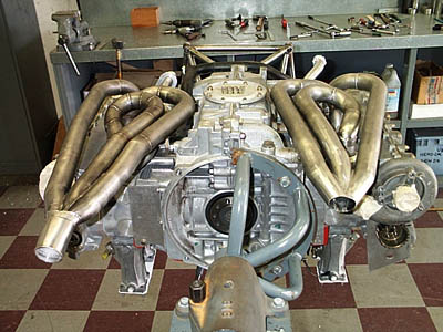
Above
is the rear end of the bottom of the motor. Note water Pump (round turbo-looking
device, just to the right of the exhaust header at far right), which is driven
off the lower cam on the left cylinder bank (right side in this photo), and there
used to be a similar pump on the other cylinder bank. Due to interference problems,
both pumps will be removed and replaced by a single, larger water pump via a "Y"
fitting. 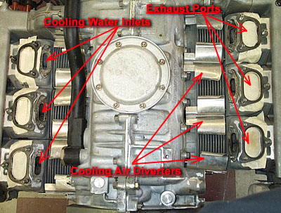
The
arrangement of the bottom side of the flat-six is clear to see, with all the various
headers and water piping removed. This is a combination water-and-air-cooled motor
- air cools the cylinders, but the heads are water-cooled. The vertical fan (see
earlier update) draws in air from in front of the motor, and diverts it down between
and around the cylinders, which are finned to add heat dissipation area. At the
bottom of the motor thin aluminum air diverters (see arrows above) are placed
such that the air coming down from above is forced around the bottoms of the cylinders
before exiting out the bottom. If these diverters were not in place, the air would
go straight out the bottom, causing the bottom sides of the cylinders to be much
hotter than the upper sides (that's not good). Also the exhaust ports can be seen,
and just inboard of them are the cooling water supply inlet ports for the heads.
You saw the radiator positions in a previous update. 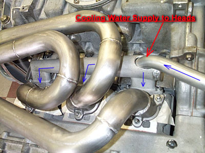
Looking
again at the bottom of the motor, specifically the left cylinder bank. Previously,
the head-cooling manifolds were oriented the reverse of what is pictured, receiving
their water supply from the back of the motor (where those camshaft-driven water
pumps were, as explained above. That was not possible in our installation due
to interference, so the water manifolds have been reversed and now take their
water supply from the front of the motor, very close to the radiator for each
bank. Here the modified exhaust header and the water supply manifold are in place,
and the supply piping to the water manifold is being fabricated to join it. The
blue arrows show the water path into bottom of the cylinder head. 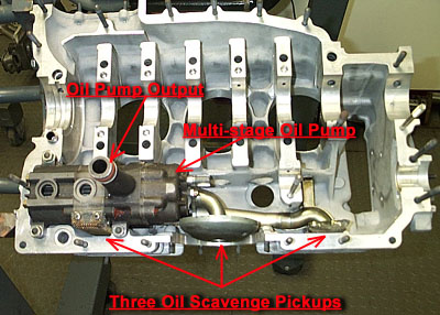
A
cross-section view of a similar Porsche crankcase shows oil pump detail. Unlike
most road cars, racing engines have "dry sump" oil systems, which means
the main oil supply is not stored in a pan below the crankcase. This is bad for
racing applications for two reasons: the extra oil sloshing around in the crankcase
robs engine horsepower, so if all the oil is quickly scavenged from all parts
of the crankcase the motor turns more effortlessly. Also, not having an oil pan
beneath the motor allows the whole package to be smaller and sit lower in the
chassis. Also a separate oil tank can hold much more volume than most oil pans
(and eliminates the dipstick!). The oil gets pumped out of the motor through the
large black pipe you see in the picture of the bottom of the motor (center, above),
and gets sent through an oil cooler, and from there back to the oil supply tank.
<<<
Previous Update | Next Update >>> |