| 
First
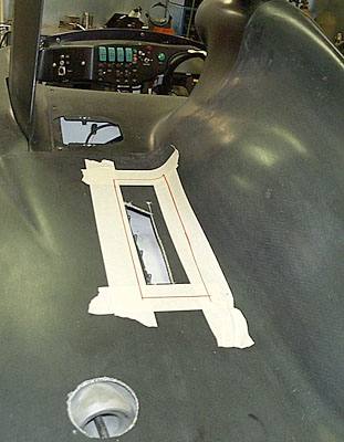
order of business is putting all the bodywork in place, and determining where
the induction risers are beneath the body. A pilot hole is cut in approximately
the right place, and then the exact limits of the opening taped and marked off,
so that the proper size and shape holes can be cut. Note that the risers aren't
going to stick up through these holes, but this is just a preliminary step in
working out the final shape of the engine cover. 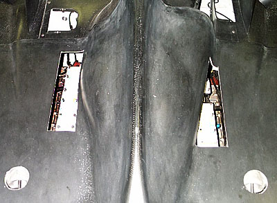
In
the photo above the engine cover is in place, and the appropriate-sized openings
have been cut into the bodywork. This is a real help in starting to visualize
the layout of the various components that will have to go under our revised engine
cover. The round holes are the beginnings of clearance "bubbles" that
will be on the engine cover, giving room for the rear shock absorber rockers.
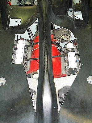
Looking
down on the now see-thru engine cover, with the motor plainly visible beneath.
Now the real cutting has started, taking into consideration that intake plenums
will be mounted atop the intake risers, and that there will be intercoolers atop
the motor as well. All these openings get revised in a later step. The "spine"
of the engine cover remains in place, at least for the time-being, to give the
whole unit some strength as we chop ever-larger sections of it away. It won't
necessarily remain once we've worked out the final shape. 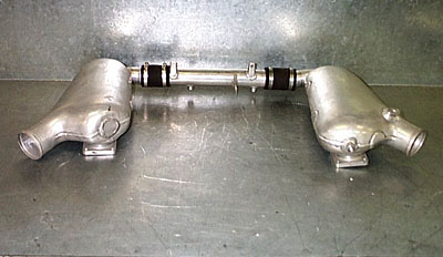
This
is an unmodified set of intake plenums for a 962-type motor. Our two-liter motor
won't require the same pressure/volume of air as the larger motor, so we'll be
making a set of prototype plenums by modifying these. 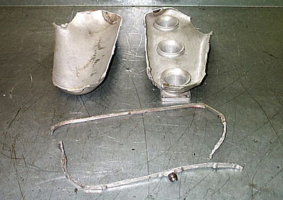
The
plenum first gets sawed in half. Then a section is removed from the middle to
reduce the height of the plenum beneath the bodywork. Above you see the top of
the plenum (upper left), the lower section that bolts to the intake risers (above
right) and below that, the section of aluminum that has been removed from around
the middle. 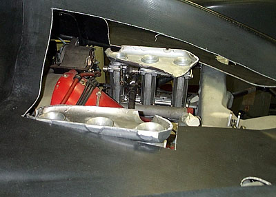
Looking
sideways through the engine cover holes, you see the two intake plenum lower-halves
attached to the risers, giving a better idea of how much clearance they'll need
in the bodywork. 
Another
shot from the back, looking through the engine cover, shows the sectioned plenums
temporarily in place, and the holes in the bodywork correspondingly modified to
accommodate their shape. Also note that the shock absorber rocker clearance holes
have been modified in shape from the simple round holes we started with. It may
all look "chopped-up" at this stage, but major progress has been made. 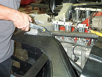
With
all the bodywork in place, including the various air ducts within the bodywork,
we can begin to trim away the existing carbon sections that interfere with the
new mechanical components. 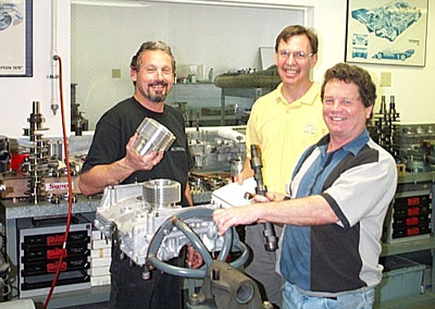
Until
now we've just been using dummy engine blocks for chassis fitting purposes, but
now the serious motor-building has begun. Dave Jarvis (right, above) will be looking
after the cylinders, heads and dyno work, and UCF engineer Dr. Todd Dvorak (center,
above) is responsible for the high-performance optimization of the whole motor
package. 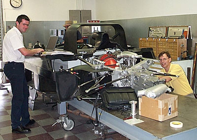
Dr.
Dvorak has been joined by Marcus Haselgrove (left, above), who is a Motec Systems
Development Engineer. The two of them are working at measuring the car for the
wiring harness it will require, specific to the Porsche application. The car currently
has a 936/956-type 2-liter, 4-cam/4-valve motor fitted, which is what will be
used at Le Mans, but will have a slightly smaller restrictor than the other motor
we'll have for this car, a 2-liter, single-cam/2-valve unit which, being a 2-valve
motor, will get a slight restrictor break. Horses for courses...
<<<
Previous Update | Next Update >>> |